Quantrex Quantrex AcademyJEE · NEET · NDA PYQs with solutions Open app
JEE Main 20209 JanuaryMorning Shift
Exam
JEE Main
Year
2020
Date
9 January
Shift
Morning Shift
Subject
Physics
Chapter
Semiconductors

JEE Main 2020 · 9 January · Morning Shift · Physics · Semiconductors

Both the diodes used in the circuit shown are assumed to be ideal...

Both the diodes used in the circuit shown are assumed to be ideal and have negligible resistance when these are forward biased. Built in potential in each diode is 0.7V0.7V. For the input voltages shown in the figure, the voltage (in Volts) at point A is ________
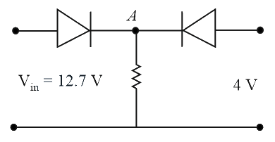
Both the diodes used in the circuit shown are assumed to be ideal and have negligible resistance when these are forward

Correct answer

0

Step-by-step solution

Both the diodes used in the circuit shown are assumed to be ideal and have negligible resistance when these are forward
Let VB=0{V}_{B} = 0
Right diode is reversed baised and left diode is forward biased
∴VA=12.7−0.7∴ {V}_{A} = 12.7 - 0.7
=12= 12 Volt
Practice Semiconductors on Quantrex Academy →

More from Semiconductors

The output Y for the given inputs A and B to the circuit is: JEE Main 2026Refer to the logic circuit given below. For two inputs (A=1, B=1) and (A=0, B=1) , output… JEE Main 2026The maximum rated power of the LED is 2 mW and it is used in the circuit with input… JEE Main 2026In a semiconductor p-n diode, the doping concentrations on p-side and n-side are 10^ 15… JEE Main 2026For the given logic circuit, which of the following inputs combination will make both LED… JEE Main 2026Given below are two statements: one is labelled as Assertion A and the other is labelled… JEE Main 2026A diode has Zener voltage of 10 V and maximum power dissipation of 0.5 W, then the… JEE Main 2026Two 4 bits binary numbers, A = 1101 and B = 1010 are given in the inputs of a logic… JEE Main 2026 Full Semiconductors list All JEE Main PYQs