
Concepts Of Physics MCQ Edition [Volume 2]
- Exam
- Concepts Of Physics MCQ Edition [Volume 2]
- Subject
- Physics
- Chapter
- Semiconductors and Semiconductor Devices
Concepts Of Physics MCQ Edition [Volume 2] · Physics · Semiconductors and Semiconductor Devices
As illustrated in the figure, two identical p - n junctions can be...
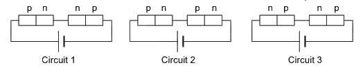
As illustrated in the figure, two identical - junctions can be connected in series with a battery in three different ways. The potential difference across the two - junctions is equal in
Options
- Acircuit 2 and circuit 3
- Bcircuit 1 and circuit 2
- Ccircuit 3 and circuit 1
- Dcircuit 1 only
Correct answer
A. circuit 2 and circuit 3
Step-by-step solution
In the given circuits, the longer line of the battery symbol represents the positive terminal and the shorter, thicker line represents the negative terminal. Thus, the left side of each circuit is connected to the positive terminal and the right side to the negative terminal.
Let us analyze the biasing of the - junctions in each circuit:
In Circuit 1, the left - junction has its -side connected to the positive terminal, making it forward-biased. The right junction has its -side connected to the negative terminal, making it reverse-biased. Since a reverse-biased junction offers much higher resistance than a forward-biased one, the potential drops across the two junctions will be unequal.
In Circuit 2, both - junctions are oriented such that their -sides are at a higher potential relative to their -sides. Thus, both are forward-biased. Being identical and connected in series, they carry the same current and offer the same resistance, resulting in equal potential drops across them.
In Circuit 3, both - junctions are oriented such that their -sides are at a higher potential relative to their -sides. Thus, both are reverse-biased. Being identical and connected in series, they offer the same resistance, resulting in equal potential drops across them.
Therefore, the potential difference across the two - junctions is equal in Circuit 2 and Circuit 3.
Let us analyze the biasing of the - junctions in each circuit:
In Circuit 1, the left - junction has its -side connected to the positive terminal, making it forward-biased. The right junction has its -side connected to the negative terminal, making it reverse-biased. Since a reverse-biased junction offers much higher resistance than a forward-biased one, the potential drops across the two junctions will be unequal.
In Circuit 2, both - junctions are oriented such that their -sides are at a higher potential relative to their -sides. Thus, both are forward-biased. Being identical and connected in series, they carry the same current and offer the same resistance, resulting in equal potential drops across them.
In Circuit 3, both - junctions are oriented such that their -sides are at a higher potential relative to their -sides. Thus, both are reverse-biased. Being identical and connected in series, they offer the same resistance, resulting in equal potential drops across them.
Therefore, the potential difference across the two - junctions is equal in Circuit 2 and Circuit 3.