
JEE Main 20265 AprilMorning Shift
- Exam
- JEE Main
- Year
- 2026
- Date
- 5 April
- Shift
- Morning Shift
- Subject
- Physics
- Chapter
- Current Electricity
JEE Main 2026 · 5 April · Morning Shift · Physics · Current Electricity
Refer to the figure given below. The values of I_1 , I_2 and I_3...
Refer to the figure given below. The values of , and are __________.
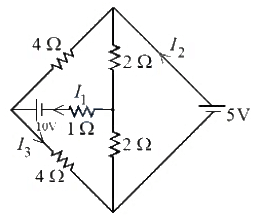
Options
- A A, A, A
- B A, A, A
- C A, A, A
- D A, A, A
Correct answer
A. A, A, A
Step-by-step solution
Using the principle of superposition, we analyse the circuit with one source active at a time.
Case 1: Only the source is active (the source is replaced by a short circuit).
With the source shorted, the top and bottom nodes of the bridge are directly connected by a wire, forming a Wheatstone bridge.
Checking for balance:
Left arm ratio:
Right arm ratio:
The ratios are equal, so the bridge is balanced. Hence, no current flows through the middle branch connecting the two nodes, and the contribution to from the source is .
Equivalent resistance of the balanced bridge:
Total resistance including the series resistor:
Current drawn from the source:
This current splits equally between the two branches, so the current through the bottom resistor is:
Case 2: Only the source is active (the source is replaced by a short circuit).
Now the source is applied across the top and bottom nodes, and the resistor lies in the middle branch between the left and centre nodes.
For the left branch ( and in series), the potential at the midpoint is .
For the right branch ( and in series), the potential at the midpoint is also .
Since both midpoints are at the same potential, no current flows through the middle branch. Hence, the contribution to from the source is .
Equivalent resistance seen by the source:
Total current supplied by the source:
Current through the left branch (which includes the bottom resistor):
Applying superposition:
Hence, the correct option is .
Case 1: Only the source is active (the source is replaced by a short circuit).
With the source shorted, the top and bottom nodes of the bridge are directly connected by a wire, forming a Wheatstone bridge.
Checking for balance:
Left arm ratio:
Right arm ratio:
The ratios are equal, so the bridge is balanced. Hence, no current flows through the middle branch connecting the two nodes, and the contribution to from the source is .
Equivalent resistance of the balanced bridge:
Total resistance including the series resistor:
Current drawn from the source:
This current splits equally between the two branches, so the current through the bottom resistor is:
Case 2: Only the source is active (the source is replaced by a short circuit).
Now the source is applied across the top and bottom nodes, and the resistor lies in the middle branch between the left and centre nodes.
For the left branch ( and in series), the potential at the midpoint is .
For the right branch ( and in series), the potential at the midpoint is also .
Since both midpoints are at the same potential, no current flows through the middle branch. Hence, the contribution to from the source is .
Equivalent resistance seen by the source:
Total current supplied by the source:
Current through the left branch (which includes the bottom resistor):
Applying superposition:
Hence, the correct option is .